

Mod Description
Yes, the smart is narrow but the lack of passenger window control on the driver's side is unforgivable.Mod Details
PremiumYes Difficulty
 Mod ID266
CreditEvilution
Cost££20
For
Mod ID266
CreditEvilution
Cost££20
For Linkhttps://www.evilution.co.uk/mod/extra-window-switch.htm Copy to Clipboard
Buy Or Make?
The 1st kit, I bought. If you want to buy one, look here.
SmartKits.net . Click here or scroll right down near the bottom of this page to see the fitting guide.The 2nd kit, I made. I had the wire and crimp terminals so all I needed was relays and the switch.
Making your own is very satisfying, not as hard as it might seem and will cost you less than £10.
Making Fitting The Home-Made Kit
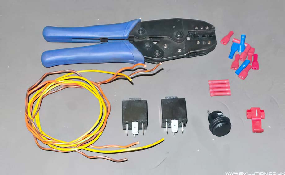
You’ll need the following:
Crimper,
Spade connectors (red and blue),
Straight through butt connectors,
2x 5 terminal automotive relays,
A centre bias (on)-off-(on) switch,
Thick and thin wire,
Soldering iron & solder or those terrible quick connectors.
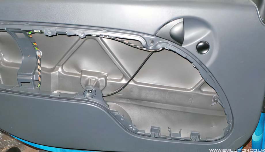
Remove the Torx25 screws from the handle and the Torx20 screws from the door pocket.
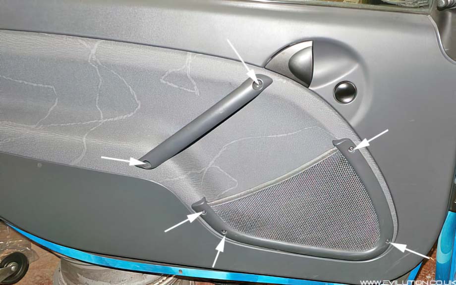
Grab the bottom of the door card and pull it to disengage the clips.
Pull the door card towards the font of the car to release. Repeat on the other side.
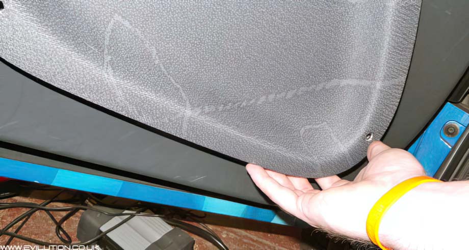
You now have access.
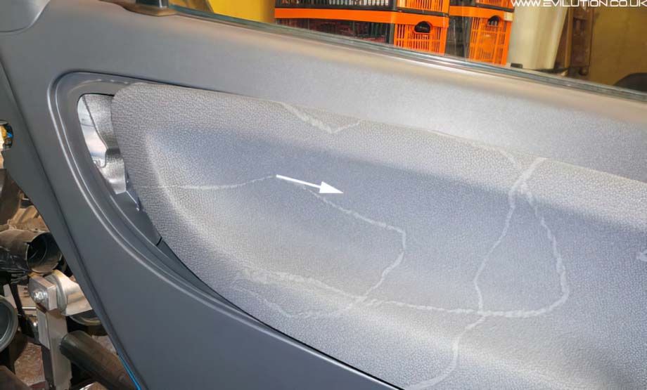
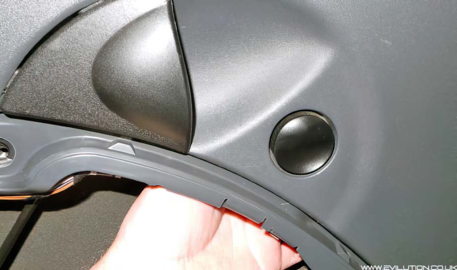
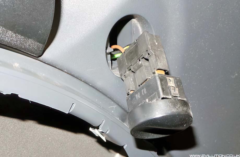
Reach behind the switch on the passenger’s side and push it out from the back.
Then disconnect the switch by pulling the unit from the connector.
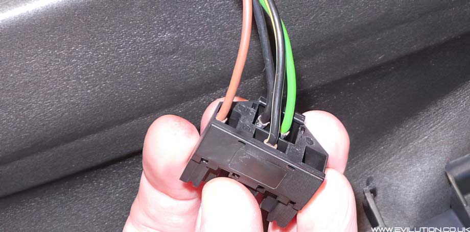
The connector has 4 wires. We will be using some of these later.
Now you need to create the wires. Take a wire approximately the same size as the wires to the standard window switch.
Crimp a red spade terminal on the end. Measure back about 5cm and cut away the sheath. Bend the exposed wire and then crimp a blue spade connector to it.
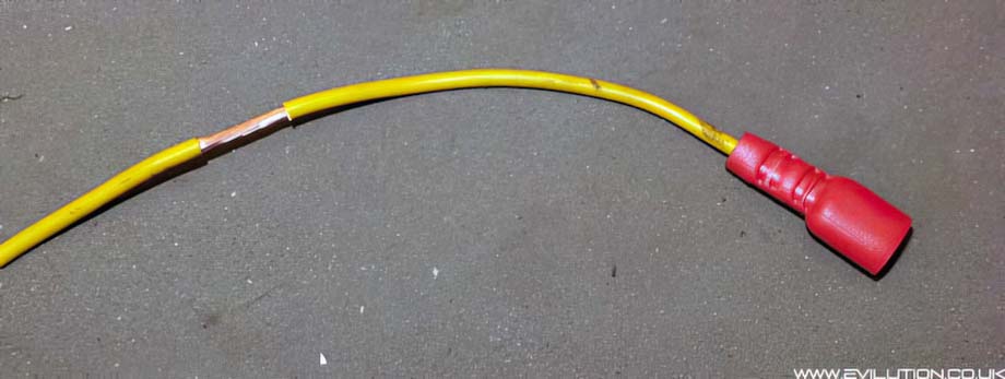
Like this…
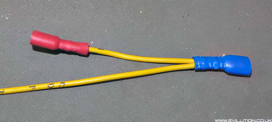
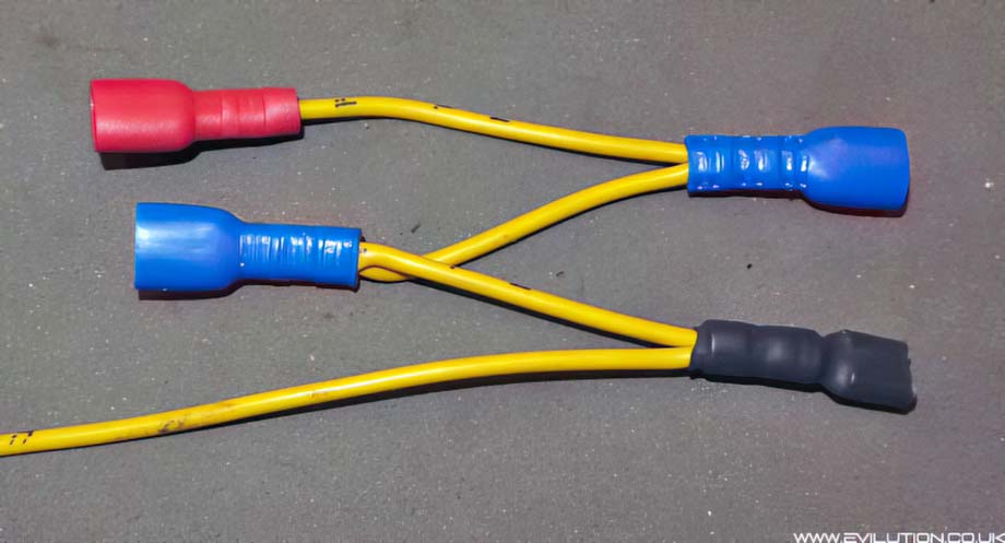
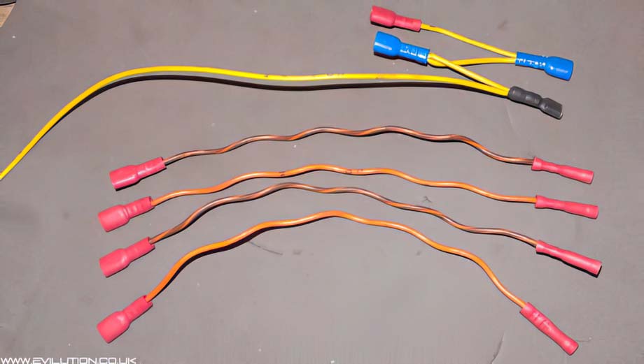
Keep doing that until you have 4 spade connectors (1 red and 4 blue) on the same wire. Make the final length of wire about 1 meter long. You only need to make 1 of these.
You’ll also need to make 4x 30cm wires with a red spade connector on 1 end and a butt connector on the other.
Take your centre bias switch and connect 4 meters of cable to each of the outside terminals. Use a 15cm piece of cable for the centre terminal.