Roadster Pods In A For2
Where the For2 gets a boring clock and rev counter, the Roadster gets a slightly more interesting coolant and boost gauge.
Please note: This can only be added if you have a 700cc smart For2.
There is a possibility it will work on the 800 CDi but it's up to you to try it.
If you do, please let me know how you get on so I can update my information.
Please also note that I was the first to do this, since then, the information has been leeched and put on other sites with no acknowledgement to myself.
Trip Computer and the 6 to 10 way adapter
If you have already fitted the Trip Computer then this is going to be very easy.
You just have to plug the pods into the spare 6 way connection in the back.
If you haven't fitted the Trip Computer and you don't plan to then that's fine.
With your dash pods you should also get an adapter cable (shown below).
The cable changes the Trip Computer connection to the pods connection.
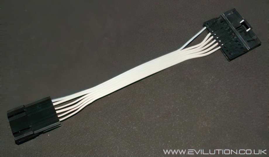
It's handy to have as you can cut off the 10 way connector and wire straight to it.
Adding the essential wiring for the Dash Pods
Sam Lin BUS wire
The Lin BUS wire is the connection that carries all the vital information to the dash pods.
On the Roadster, the Lin wire is already present but not so on the For2, let's add it.
Drop the SAM unit down, the nearest part to you is the hinge, reach to the back and pull the plastic loop. The SAM should swing down and you should be able to gain access to the connector we need. If not you will have to disconnect the hinge by pushing it up and towards the front of the car. A full How2 will be added soon.
The connection we are looking for is labled N11-9.
To remove the plug you simply press the clip in and swing the plastic
lever over (exactly like the speedo connector).
As the lever swings it will push the connector out, you will see that the large white block houses 2 smaller AMP connections, 1 black and 1 grey.
Slide out the grey connector from the white block.
Look at the side of the grey block and you will see numbers at the ends 1, 10, 11 and 20.
This makes it easy to find empty connection 14, it is next to the all blue wire.
In the frame below you can see the wire I have attached, the terminal just pushes and clips in place. I was lucky to have some pre-wired terminals the correct size that I got from another smart. All the AMP connections use the same terminals so get looking, if you have problems let me know, I may have some spare.
With the new wire connected, slide the grey block back into the white holder.
Push it back into the SAM unit and fold the lever back over to lock it in place.
Check the car still works before putting the SAM unit back under the dash.
What wires go where?
This shows the wiring of the adapter, it has a single blue wire and 5 grey.
If you remember that the blue wire is wire number 1 you shouldn't go wrong.
Pods Connection 1- Radio A6 wire colour Green/blue.
If you are just having the extra pods you do not need to bother with this connection.
This wire is the dimming signal used by the trip computer.
Remove the stereo and look at the lowest connector seen here, Grundig I/O.
You will find a green/blue wire going to pin 6 which is the lighting input.
Using your favourite method (scotchlock connection, crimp connections etc) add a trailing wire to this green/blue wire. This will eventually wire to the pods connection 1.
Pods Connection 2- Lin BUS connection.
This is the wire that you attached to the SAM unit earlier on.
This wire will eventually connect to the pods connection 2.
Pods Connection 3- Earth
Connect a wire to a good earthing point on the car, there is one in each footwell.
This wire will eventually connect to the pods connection 3.
Pods Connection 4- Fuse 11, 7.5A
The easiest way to gain access to fuse 11 is through the OBD port.
Use a suitable pin to fit the OBD socket and wire it from there.
This wire will eventually connect to the pods connection 4.
Pods Connection 5- Fuse 20, 15A
The easiest way to gain access to fuse 20 is through the OBD port.
Use a suitable pin to fit the OBD socket and wire it from there.
This wire will eventually connect to the pods connection 5.
Pods Connection 6- Fuse 6, 7.5A
Remove the stereo and look at the lowest connector seen here, Grundig I/O.
You will find a green/blue wire going to pin 6 which is the lighting input.
Using your favourite method (scotchlock connection, crimp connections etc) add a trailing wire to this green/blue wire. This will eventually wire to the pods connection 7.
Fitting the pods to the car
Now you have wired it all up to the adapter, plug the pods in to check they work.
The turbo gauge can be seen to work straight away and so can the lighting behind the dials.
You will have to drive the car to full operating temperature (3 blobs = 80C) to make sure it works and that it is accurate to the gauge on the dashboard.
There are loads of ways that you could attach the pods to the car, I personally used the bases from a pair of original For2 pods. In this case I destroyed 2 rev pods just for the base.
Here is what you get when you buy the Roadster dash pods.
Look underneath and remove the torx screws.
The plastic retainers should slide out and unclip from the ribbon cable.
Pull out the single connector...
...and both pods will come away from the base.
If you look you will notice that the pods have a 10mm neck underneath,
this is perfect for fitting to the base of the For2 pods.
I forgot to take pictures from this point but it's a very easy task to complete.
You need to find a bit of plastic tube that sits over the neck of each pod.
Cut the pipe short and push it onto the For2 base, you may need to file
the inside of the pipe until it fits both ends.
Glue leather onto the plastic pipe or paint, reconnect the wiring underneath.
Hide the wires down behind the centre console, wire them up and fix
the new pods to the dashboard. Turn on the car and test them out once again.