Narrow your search
Modification Details
Translate Evilution
german french spanish italian greek finish danish polish japanese russian
Search Evilution
Most Viewed Pages
Most Rated Pages
451 Heater Controller LEDs
How to change the SMD LEDs in the 451 heater controller
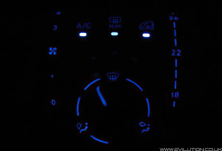
 Most of the SMD LEDS on the 999cc Fortwo are PLCC-2 (TANTAL/B) and they 
are a very common fitment. Some of these are dome lens type.
Some of the fiments are dome lens PLCC-4, this is unique to the new smart.
There are also some much smaller LEDs being used. These are 0805 package LEDs.

This is where I got mine from, clicky.

I'm Too Scared To Do This, Who Can I Pay?

CrazyLeds can change y
our SMD LEDs for you. Just ask them.


Dome Lens Info

The transparent dome narrows the spread of light and evens out the brightness.

SMD Orientation

Like most LEDs, they only work one way around. Standard LEDs are marked 
with a single flat edge and 1 shorter leg. The SMD LEDs have a recessed 
triangle in the corner, these are marked as red in the pictures.

Soldering SMD LEDs

The first job is to remove the existing LEDs, you have 3 ways to remove them:
1. Use two soldering irons, one on each joint and flick the LED off;
2. Use one soldering iron and a solder sucker, can be awkward because of the size;
3. Use one soldering iron and some solder wick to remove the excess.

Once the board has been purged of LEDs, clean the board up and flux the solder pads on the board and LEDs. Position one of the replacements and quickly solder each side.

The 'normal' way to solder is to touch the tip to the device and push the solder against the tip and the device until it melts. When soldering SMDs this isn't recommended as the heat will kill it.
It is better to melt the solder onto the tip and quickly dab the soldered tip onto the LED, this limits the heat transfer, flux will help the solder flow to the LED quickly shortening the time even more.

Once they have all been done, visually check the whole thing before testing, if any of 
them don't work then check the solder joint and the orientation of the LED.

Heater Controller

This is the last and hardest part to change the LEDs on because it's awkward to open.
Remove the heater controller by following the 1st part of this guide.

Set the fan speed to setting 2 and the heat to setting 22. (This lines up internal tabs).


Look on each side and you will see 2 rectangle openings. Place a screwdriver in
each side and lever the tabs towards the centre. You can then pull the dials off.


Here you can see the tabs below and the holes above it.


Remove the 4x Torx10 screws.


Carefully lever the knob off from top and bottom.


You can see that the knob is held to the shaft with 2 small tabs.


You will now be able to separate the front and back to access the PCB.


Be aware of the ribbon connector to the cabin temperature sensor. It  can't be disconnected
so be careful that you don't pull on it or snag the cable. Thanks to Chi M for the picture.


Flap the PCB over to reveal the SMD LEDs. You have 4x PLCC-2 and 6x 0805 LEDs


Each of them is labelled on the PCB with a K which denotes the cathode of the LED.


The cathode is the negative terminal of the LED. The negative side will either be denoted with an
arrow (the point of the arrow is the cathode side) or there will be a corner cut out of the LED.


Once you have desoldered the new SMD LEDs in place you can reassemble the unit.
Leave the main shaft and the knob off for the moment so we can calibrate it on the car.


Heater Controller Calibration

Did you realise that when the knob is facing the windscreen, the air conditioning comes on
at a low level and if the air recirculation is selected, it is automatically deselected? We need
to make sure that when the shaft and knob is replaced, it activates this in the right position.

Push the shaft into the back of the controller in any position.


Plug in the 2 block connections.


Turn the ignition to position 1 and press the recirculate air button so the light comes on.


Rotate the shaft 1 click at a time until the light goes out.


Push the shaft inwards. Once pushed in, spin it round...


...so the small tab faces down and the large tab faces up.
Pull the main shaft back out into its correct position.


Hold the back part of the main shaft and push the knob into position facing straight up.
Test that the recirculate light goes out when the top setting is selected.


And when any other setting is selected, the recirculate light comes back on.


The heater unit is now calibrated so now you can refit it to the car.

The blower position sensor cable will only push back into the heater controller unit
one way around as it has 1 large and 1 small tab. It is important not to pull this
cable because if it detaches from the other end it is hard to reconnect.


With the selector cable clipped in, all 3 electrical connections inserted correctly, the 2 Torx
screws refitted to hold the unit in place and the dash centre surround in place, you are finished.


Wait until it gets dark and check out your new illuminations, nice!


Click if Info Helpful

Buy me a drink

Contact us about mod

Print page

Translate

Back to top