

Mod Details
PremiumNo Difficulty Mod ID1098
Creditevilution
For
Mod ID1098
Creditevilution
For


 Linkhttps://www.evilution.co.uk/mod/connection-reference-numbers.htm Copy to Clipboard
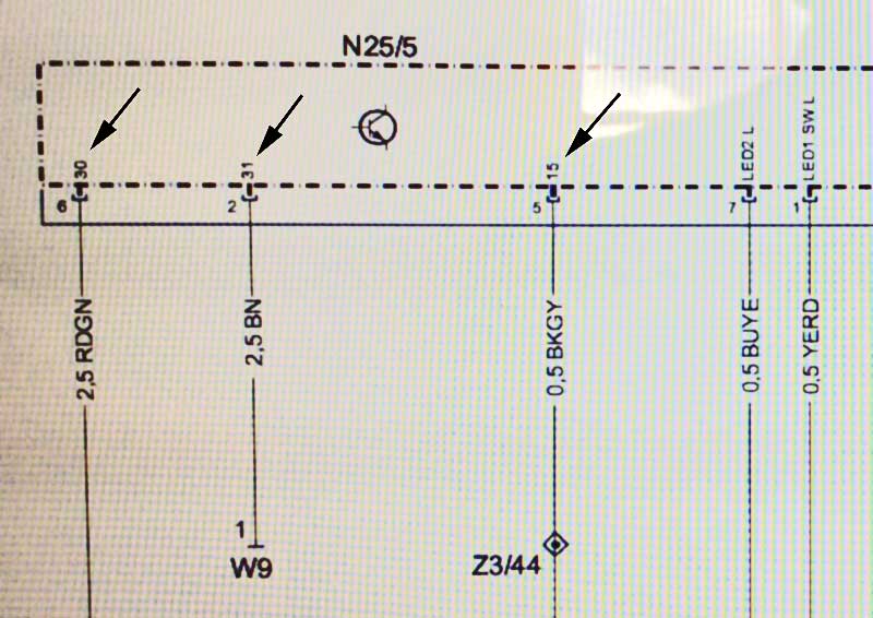
KL is the abbreviation for ‘klemme’ which is the German term for connector / connection. The Klemme KL code tells you how a power or earth wire functions on a diagram.
Used On Smart Wiring Diagrams
KL15 is ignition switched live
KL30 is battery permanent live
KL31 is battery negative, connected all the time
Not Used On Smart Wiring Diagrams
KL50 is ignition position #3 (start)
KLR means ignition switch position #1 (accessory)
Ignition Switch Position
Ign 1 – KLR
Ign 2 – KL15
Ign 3 – KL50
Smart Ignition Switch Positions
Smart only use 3 positions unlike many other cars that use 4.
Off
Accessory
Start
How Is This Handy?
Well, to be honest, for you it might not be but I look at smart wiring diagrams every day and I really needed somewhere I could put this information so I could quickly view it to refresh my memory.
DIN 72552
Ignition Coil
1 Low voltage
4 High voltage
4a From ignition coil I, terminal 4
4b From ignition coil II, terminal 4
15 Switched positive after battery (ignition-switch output)
15a Output at the series resistor to the ignition coil and to the starter
Glow-Plug And Starter Switch
17 Start
19 Preglow
Battery
30 Line from battery positive terminal (direct)
30a Battery changeover 12/24 V Line from battery II positive terminal
31 Return wire from battery negative or ground (direct)
31b Return wire to battery negative or ground via switch or relay (switched negative)
Battery Changeover Relay 12/24 V
31a Return line to battery II negative
31c Return line to battery I negative
Electric Motors
32 Return line
33 Main terminal
33a Self-parking
33b Shunt field
33f for second reduced-rpm operation
33g for third reduced-rpm operation
33h for fourth reduced-rpm operation
33L Rotation to left (counterclockwise)
33R Rotation to right (clockwise)
Starter
45 Separate starter-motor relay, output; starter, input (primary current)
Dual Starter
45a Starter I output, Starter I and II input
45b Starter II output
48 Terminal on starter and start repeating relay (monitoring the starting process)
Turn-Signal Flasher
49 Input
49a Output
49b Output to second flasher circuit
49c Output to third flasher circuit
Starter
50 Starter control (direct)
Battery Changeover Relay
50a Output for starter control
Starter Control
50b In parallel operation of two starter motors with sequence control
Starting relay for sequence control of engagement current in parallel operation of two starter motors
50c Input at starting relay for starter I
50d Input at starting relay for starter II
Start-Locking Relay
50e Input
50f Output
Start Repeating Relay
50g Input
50h Output
Wiper Motors
53 Wiper motor, input (+)
53a Wiper (+), self-parking
53b Wiper (shunt winding)
53c Electric windshield-washer pump
53e Wiper (brake winding)
53i Wiper motor with permanent magnet and third brush
for higher speed)
Lighting
55 Fog lamps
56 Headlamps
56a High beam with indicator lamp
56b Low beam (dipped beam)
56d Headlamp-flasher contact
57a Parking lamp
57L Parking lamp, left
57R Parking lamp, right
58 Side-marker, tail, license-plate and instrument lamps
58d Adjustable instrument lighting
58L left
58R right
Alternators And Voltage Regulators
61 Alternator charge indicator
B+ Battery positive terminal
B– Battery negative terminal
D+ Alternator positive terminal
D– Alternator negative terminal
DF Alternator field winding
DF1 Alternator field winding 1
DF2 Alternator field winding 2
U, V, W Three-phase terminals
Audio Systems
75 Radio, cigarette lighter
76 Loudspeaker
Switches – Normally Closed Contact/Changeover Contact
81 Input
81a 1st output, NC side
81b 2nd output, NC side
Switches – Normally Open Contact
82 Input
82a 1st output
82b 2nd output
82z 1st input
82y 2nd input
Multiple-Position Switch
83 Input
83a Output, position 1
83b Output, position 2
83L Output, position left
83R Output, position right
Current Relay
84 Input, output, relay contact
84a Output, drive
84b Output, relay contact
Switching Relay
85 Output, drive (end of winding negative or ground)
86 Input, drive (start of winding)
86a Start of winding / 1st winding
86b Winding tap / 2nd winding
Relay Contact For NC Contact And Changeover Contact
87 Input
87a 1st output (NC side)
87b 2nd output
87c 3rd output
87z 1st input
87y 2nd input
87x 3rd input
Relay Contact For NO Contact
88 Input
Relay Contact For NO Contact And Changeover Contact (NO Contact Side)
88a 1st output
88b 2nd output
88c 3rd output
Relay Contact For NO Contact
88z 1st input
88y 2nd input
88x 3rd input
Turn-Signal Lamp (Turn-Signal Flasher)
C 1st indicator light
C0 Main terminal for check circuits separate from flasher
C2 2nd indicator lamp
C3 3rd indicator lamp (e.g for dual trailer operation)
L Left-side turn-signal lamp
R Right-side turn-signal lamp