

Mod Details
PremiumNo Difficulty Mod ID1552
Creditevilution
For
Mod ID1552
Creditevilution
For Linkhttps://www.evilution.co.uk/mod/roadster-wastegate-actuator-hoses.htm Copy to Clipboard
Understanding Engine Hose Position
If you have a BCS (Boost Control Solenoid AKA Cycle Valve) as most new smarts do, you will notice that there is a maze of pipes surrounding the turbo. So here is a roundup of where they come from, the colour and where they all go.
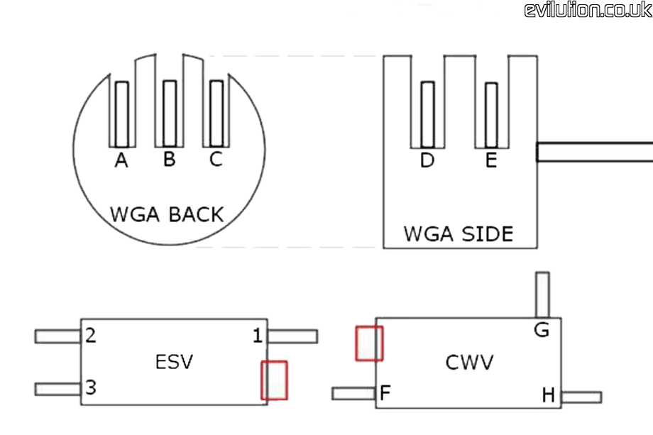
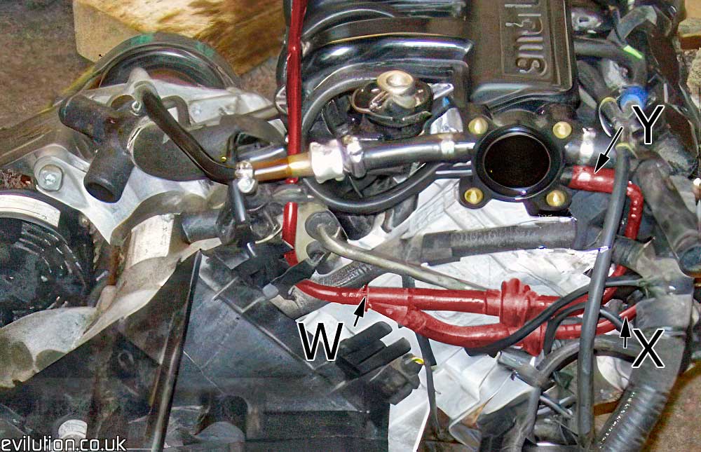
First up we will start with some pictures that show the starts or ends of each pipe.
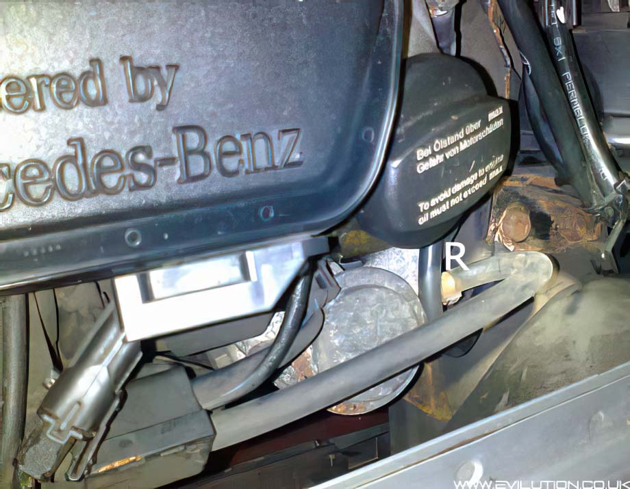
WGA = Wastegate Actuator (attached to the turbo).
CWV = Cycle Waste Valve (front of the TIK pipe plate).
ESV = Electric Switching Valve (rear of the TIK pipe plate)
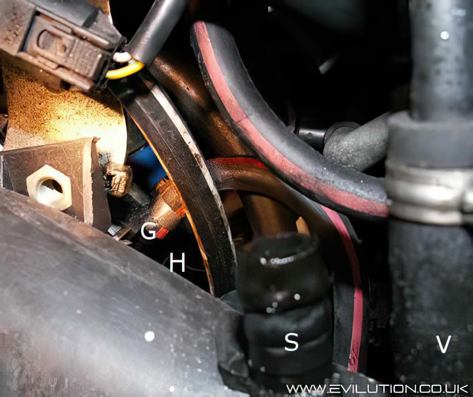
The red boxes show the location of the wiring connectors.
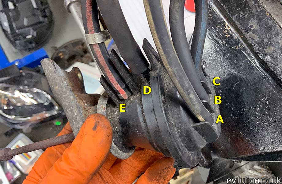
Each hose connection is labelled with a number or letter.
The CWV unit actually has the numbers marked on it.
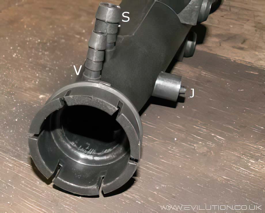
New Style Actuator
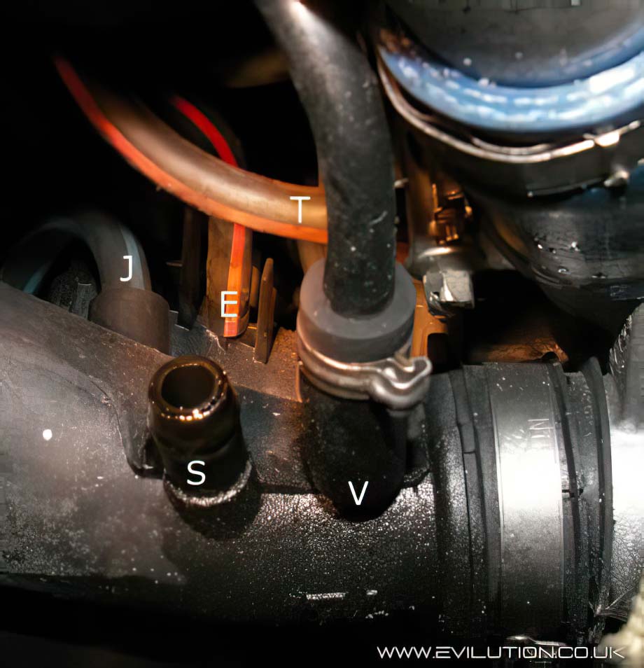
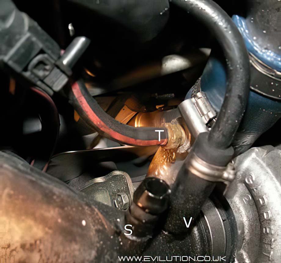
This shows the TIK pipe that joins the air box to the turbo. Note the connector on the back (J) and the 2 barbed connections on top (S and V).
“S” is the connection for the lower engine breather pipe. It is a short right-angled rubber pipe that passes burnt oil vapour into the TIK so it can enter the engine to be burnt in the combustion cycle.
“V” is the fuel tank breather pipe. Air is drawn into the fuel tank from here so there is no vacuum.
Here is a slightly clearer overall layout of the pipes.
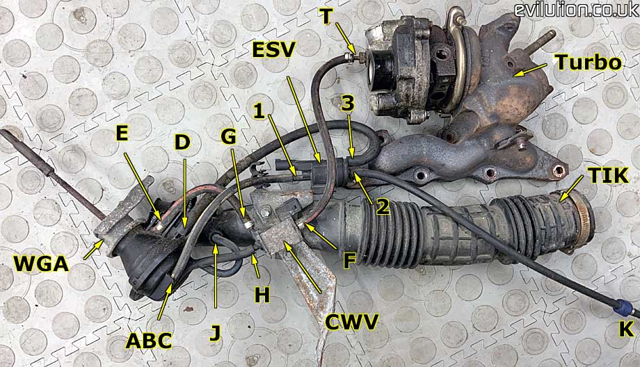
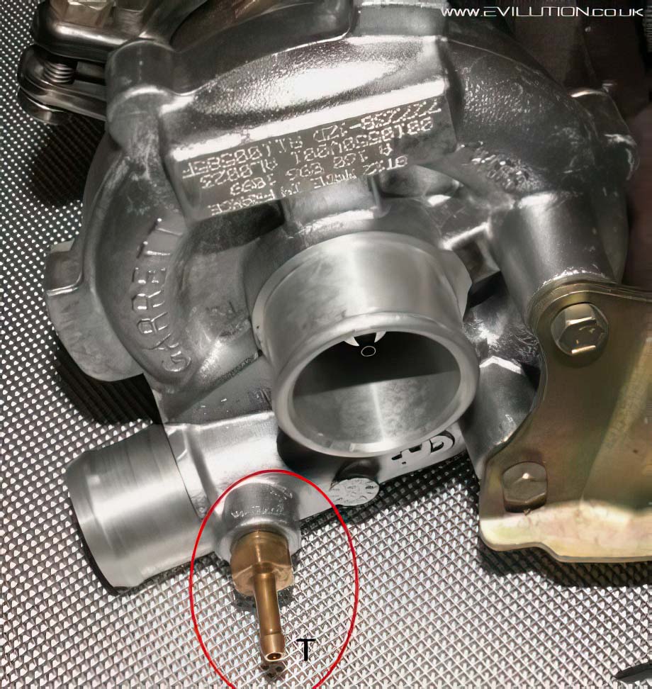
This shows the turbo inlet rotor housing. Note the brass connector on the front (T). This passes boost air to the Boost Control Solenoid (BCS).
At the top of the engine you will find this hose splitter, The single connection is (K). The 2 hoses coming from it (L & M) are waste gas emission hoses.
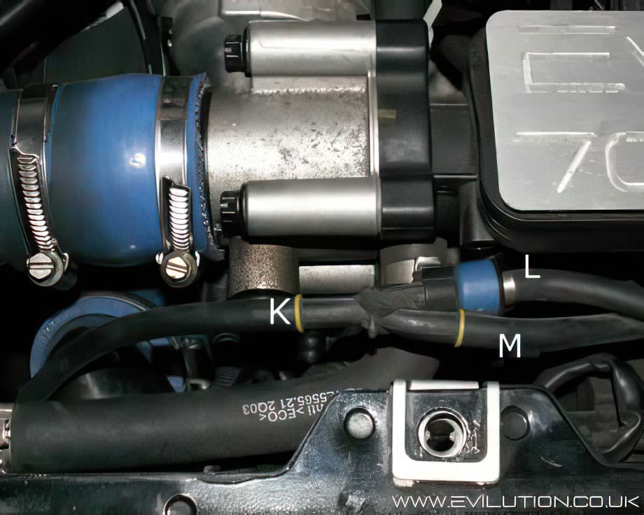
Connection L contains a small check valve to stop boost air passing to the cycle waste valve (CWV).
Connection L joins to connection N on the front of the air intake manifold.
Connections P & Q are part of the secondary air injection valve selector.
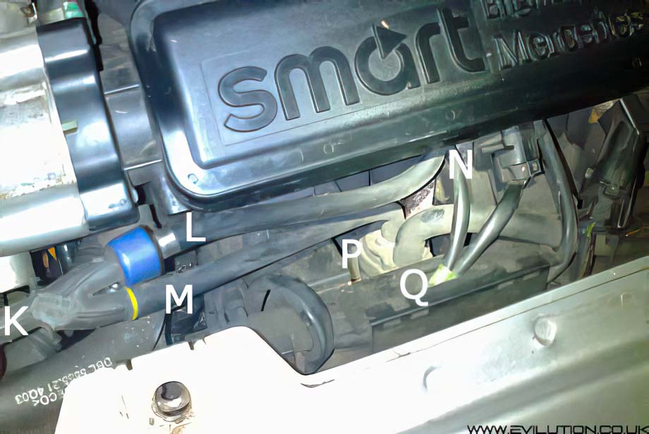
The valve (connections P, Q) has an unused connection underneath. This is just left open. (thanks Christian K for the photo).
Connection Q from the change-over valve joins to connection R of the secondary air injection switching valve.
Understanding the pipe colours and routes
| From | Pipe Colour | To |
| A | Black with white stripe | 1 |
| B | Black | H |
| C | Black with blue stripe | J |
| D | Black | 3 |
| E | Black with red stripe | G |
| F | Black with red stripe | T |
| G | Black with red stripe | E |
| H | Black | B |
| J | Black with blue stripe | C |
| K | Black | 2 |
| L | Black | N |
| M | Black | P |
| N | Black | L |
| P | Black | M |
| Q | Black | R |
| R | Black | Q |
| S | Black | Engine |
| T | Black with red stripe | F |
| V | Black | W |
| 1 | Black with white stripe | A |
| 2 | Black | K |
| 3 | Black | D |
Cross Reference Pictures
Here are a few pictures to show the hoses in situ and their connection identifier. It is worth pointing out that connections A, B and C are all the same and are interchangeable.

Follow the directions carefully and it soon becomes clear.